(Click title above for PDF download)
Introduction
This Application Note is intended to describe CPU to CPU communication with FabreX.
This discussion pertains to any resource that has some sort a processing element in it with a supporting (RCP) Root Complex Processor that is able to enumerate PCIe (PCI Express) I/O devices. Consequently, resources such as FPGA, AI ASICS, intelligent storage, embedded controller, etc. can all potentially fall under this category labeled ‘CPU’.
The Basics of CPU to CPU Communication
The discussion in this document is confined to traditional CPU architecture as prevalent in servers. However, it can be extrapolated to other intelligent agents alluded to in the previous section.
Figure 1 depicts such a traditional architecture, where it shows ‘n’ number of servers communicating amongst themselves. The dotted lines show the communication paths from a conceptual standpoint.
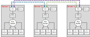
Figure 1 –Traditional Server Architecture
This figure also shows the fundamental architecture of the CPU ecosystem present in practically all servers.
CPUs do not have the capability to directly read/write each other resulting in the inability to directly communicate with each other.
The memory associated with the individual CPU is what is used as an intermediary resource to pass messages between CPU. There are also sophisticated techniques to inform CPUs of pending messages waiting to be serviced that originated from another CPU. In PCIe technology this mechanism is a vectored interrupt operation consisting of a memory write to a specific memory address location to the receiving agent by the sending agent.
Figure 2 shows the traditional CPU architecture in server environments. CPUs generally have multiple cores with their own exclusive L1 and L2 cache that simultaneously execute individual threads to boost the overall throughput of the CPU.
A point to note here is that there is a PCIe interface to the system memory consisting of DDR3/4 memory devices as well as the L3 cache that can be shared by all the cores. This also shows the entire System memory of the CPU as well as the L3 cache mapped within the PCIe memory space of every server via the built-in PCIe interface.
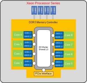
Figure 2 –Traditional CPU Architecture
FabreX Technique for CPU to CPU Communication
FabreX uses a technique whereby the FabreX switch controller under the direction of and in cooperation with the Operating System of the server maps a segment of the pertinent system memory physical space reserved for communication to a virtual address space within the FabreX domain.
Figure 3 shows an example of this. All of the individual system memory windows of the respective servers as depicted in Figure 1 are assigned a memory window of the same size in the 64-bit Global Virtual Address Space of FabreX, i.e. there is no physical memory resident in this space. The memory window sizes shown of the respective servers can be different from each other and mapped to any arbitrary physical address of the server’s system memory. These parameters are coordinated between the OS running on the various Servers and the FabreX Switch Controller resident in the Switch.
One point to note is that these windows in the Virtual Address space are absolutely unique with no overlap whatsoever.
These Virtual Memory windows do not necessarily have to correspond to server system physical memory but instead can be a block of physical memory that can be shared by all servers attached to FabreX.
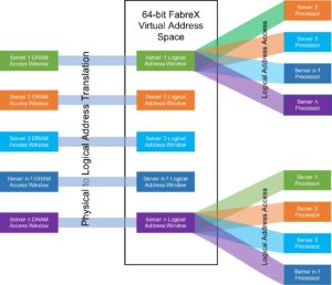
Figure 3 – Virtual Memory Space
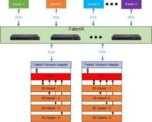
Figure 4 elaborates on this concept. This shows a non-volatile memory constituting 3D-XPoint technology as the shared memory for this architecture. This was selected on account of this being cell addressable non-volatile memory with fast access times, and unlike NVMe, it is not block addressable.
This diagram depicts how a FabreX centric system is architected for CPU to CPU communication.
This shows every server has a space dedicated in its physical memory that is accessible by all other servers attached to FabreX. Obviously there needs to be memory protection and some rudimentary protocols to prevent over writing of the message or communication space, whose implementation falls under the domain of the specific applications running on the servers.
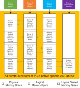
Figure 4 – Physical to Virtual Translation
This figure highlights one approach of communicating between servers where the servers system address space is divided into physical memory windows supported by memory hardware devices and logical memory space where the physical memory devices are located remotely. All of these spaces fall under the PCIe addressable space of every individual server. Again, all of these assignments are coordinated and implemented by the Servers and the Switch Controller at Boot time.
Incidentally, in some implementation the entire system memory of all servers can made to be visible to all other servers. This would be an ideal solution as long as the software running in individual severs were disciplined to not access protected memory regions of system memory of the individual servers.
The Final Solution
Figure 5 depicts a deployment of this architecture with FabreX.
It should be obvious from the discussion as to how FabreX is truly a memory centric network. Communications between agents boil down to the very fundamental rudimentary operations of ‘Load’ and ‘Store’.
Moreover, this communication path is bolstered by the robust protocol of PCIe, which is currently unmatched in the industry.
About GigaIO
GigaIO has invented the first truly composable cloud-class software-defined infrastructure network, empowering users to accelerate workloads on-demand, using industry-standard PCI Express technology. The company’s patented network technology optimizes cluster and rack system performance, and greatly reduces total cost of ownership. With the innovative GigaIO FabreX™ open architecture, data centers can scale up or scale out the performance of their systems, enabling their existing investment to flex as workloads and business change over time. For more information, contact the GigaIO team at info@gigaio.com or schedule a demo.